Friday, 10 January 2025

Houdini Workshop Week 1 - Spring 2025

     We're making a new project this semester, focused on learning Vertex Animation Textures (VATs). You're going to need to make a Houdini Project, as well as an Unreal Project inside the Houdini Folder. We'll be using Houdini 20.5 and Unreal 5.4.

    Then navigate to 

C:\Program Files\Side Effects Software\sidefx_packages\SideFXLabs20.5\unreal\5.4

    You'll want to grab the SideFX_Labs folder you'll find in here. Copy it, and then go to your unreal project. If it doesn't have a plugins folder make one. Paste the SideFX_Labs in here. 


    In your Unreal Project, go to settings>plugins, search for sideFx labs in unreal. It should be turned on. 


Starting the Houdini File

3 Ways of Exporting data
  • Rigid Bodies: Static meshes, animation per chunk, very inexpensive.
  • Cloth Sim (Constant Topology): Same topology through entire simulation, setting position and normals of mesh over time. Anything that keeps the same topology over time can be animated with cloth sim (could animate facial animation).
  • Fluid: Changing topology, fluids, volumes, some color information. Could animate fire with this as well.
    Start with a Geometry node named 'RBDVATs'.
    Bring in any test geometry. At the top left there's a Model Shelf, where you can find a shatter button. Click on it. You can then use an exploded view node to see how its fractured. 
    Usually when you model in Maya, you're modeling manifold geometry, geometry that surrounds the volume. You aren't modeling the inside. What you did here is converted the geometry here into a volume, basically using Voxels. Then the scatter node creates points within the volume. The amount of points translates to the amount of pieces you want your model to break into. 
    You usually don't want to use voronoi to fracture it, however you can use it to break into big pieces, then continue to break up each subsequent piece so it looks more natural. 
    You can also use a rbd material fracture node. Inside the parameters you can also adjust what kind of material is fracturing. The default is concrete. 

    Next we want to get rid of the material. Look for an attribute delete node. In the primitive attributes dropdown, look for 'shop_materialpath' to get rid of it. 

    Next make a switch node. Connect the rbd material fracture node first and then the voronoi fracture second. Now you can select which fracture version you want by changing the 'select input' paramter. 

    You can name the switch node 'FracturedCharacter'. 
The network so far

    Applying the RBD solver

    NOTE: Chris showed us the DOP network way. Doing it this way for some reason did not let us use the attribute wrangle node to apply the explosion. I'll show both ways but I prefer the rbdbulletsolver node. Will update when we find a solution to the DOP network issue. 

    Now go up to the object view in the network. On the top right shelves, there should be a Rigid Bodies shelf. Look for RBD Fractured Object. 
    It'll bring up this menu. Choose RBD Packed Object
    Back in the RBDVATs node, we can see this added a rest node, packed our geometry into primitives and then created another null node named TO_DOPs and then another dop network import. You can see your simulation with the dopimport node. Your character should fall/. That means it's working.
object level
    Back in the objects network. you'll see the autodopnetwork node, its where you'll do your all your physics. With any kind of simulation networks, you're configuring the physics server of the simulation. 
    Look for the Collisions tab in the top right of the shelves. Look for a ground plane and select it to bring a groundplane_object. Ground planes look like it ends but they go off into infinity.
    (I went back and added a transform node to our object and translated it up it falls onto the ground plane instead of being inside it)
    When playing the simulation it can appear fast. Select the clock on the timeline to view the simulation in real time.
Current Network

    OTHER WAY OF SETTING THIS UP Look for a RBD bullet solver node and add it after the packed primitives. Go into the parameters, look for Collision> Ground Type > Ground Plane.
    
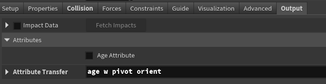
    IMPORTANT ATTRIBUTES TO ADD: Exporting just this will not work. The VATs export node needs more attributes in order to work. Go into the rbd bullet solver node > output > attribute transfer > you need to add the attributes 'pivot' and 'orient'. It won't work without it.
    You can connect the bullet solver node to a null node named OUT and you're done. Simulation should play. 

Adding the explosion effect. 

    Look for a sphere node. Position this near or inside the test geometry. Name the sphere 'bomb'. 

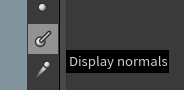
    Now you need a normal sop. You're calculating a normal for all the faces of the sphere. Click this icon to the left of the viewport to see the normals.

    What we want to do is transfer the normal directions of the sphere to the test geometry. Create an attribute transfer node and hook it up to the packed primitives node and the normal node you just made.
using an add node to visualize the transfered normals. delete the add node afterwards

    Now look for a point wrangle node. We're going to write a couple lines of VEX here. 


    Write This in the VEXpression box: 
v@v = v@N;

    The @v is creating a new attribute at every point. We're creating it and naming it v, which stands for velocity, and we're make the velocity attribute equivalent to the normal vector of that point. You can even add a parameter to control as well.
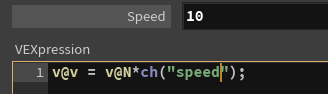
v@v = v@N*ch("speed");
    Now go back to frame one and replay the simulation. You should see your geo explode away from the position of the sphere.

Exporting

    On the object level, make a rop network. Search for vertex animation and select the Labs Vertex Animation Textures node. 
    You don't have to change too many parameters here. 
    Make sure the mode is Rigid-Body Dynamics and the output engine is Unreal Engine since that is what we will be using. For the input geometry look for the output null node that you made. Make sure you select 'export relative path (so that the text will have ../.../). 
    Tip: If you name your output node in all uppercase, it will show up first in the houdini outliner when choosing inputs. 
    That should be all you need. Hit Render All. It might take awhile to bake out the frames.     
    When you export it, you can find it in your exports folder (if you set your houdini project correctly) and you will get an fbx and three textures (the color, position, and rotation). The fbx is the initial state of your geometry. 
they come in these folders

Unreal Time

    When you import the fbx, turn off all the options. The only settings you should have on are: 
  • Vertex Color Import Option: Replace
  • Transform Vertex to Absolute: Yes
  •  Normal Import Method: Import Normals and Tangets
  • Convert Scene: Yes
  • Override Full Name: Yes
  • Material Import Method: Do not create Material
  • Reorder material to FBX order: Yes
    If you need mesh lods you can turn it on but we don't need it, so we'll keep it off. 

Texture Settings

    Importing the exr textures as normal. Open one of them and change these settings:     
  •    Use Fast MipGen Filter: Yes
  • Compression settings: HDR (RGBA16F, no sRGB)
  • Texture Group: 16 Bit Data
  • Mip Gen Settings: NoMipmaps

    We change these settings so that unreal does not do any math calculations on the colors that hold our data.    
    If you look at the texture images themselves, you'll see they're broken up into columns. The columns represent the data for every individual point.

Material

    Create a new material. With the new material selected turn off tangent space normals and also change Num Customized UVs to 6

    In the material graph, look for VAT RigidbodyDynamics node. Plug in these inputs

    You're done with the material. Create a material instance and add all the textures to the Houdini VAT parameters

    That's it. Now assign this material to the fbx. Brining it into the scene will automatically start playing the VAT.

Thursday, 9 January 2025

Lighting Workshops Week 1

 When looking for references for lights, look at movies do not look at games. Lighting artists use movies to reference lighting, and then from there have to optimize it again. If you look at game lighting you're looking at a watered down version of what they were referencing. 

Settings to make sure that Lumen is working

    When you first make a project, make sure that you select Raytracing to be on. 

Project settings


 Project > Description > Under Targeted RHIs > Default RHI > DirectX12  is selected
SM6 Should also be checked on


Engine > Go to rendering >  Global Illumination> dynamic global illumination method > Lumen should be selected
Reflection method should also be Lumen


Lumen > use hardware Ray Tracing when available checked on 

Ray lighting mode: surface cache

Software ray Tracing mode: detail tracing


Shadow map method = virtual shadow maps

    Don't turn on ray traced shadows yet. Only turn it on when you're getting banding on the shadows or noise, otherwise you can set it per light to turn it on. Turning it on by default is computationally very heavy. 

In the Scene

Two lighting setups: static (baked lighting) and dynamic. 
    Static is when you put lights in the scene, and then you save that information into the game. It is a one time computation, you don't need to compute it again if nothing changes. It does not take any extra resources when running the game. Biggest thing is that you can't get shadows, no real time. It bakes onto textures.
    Dynamic is real time lighting. This is what Lumen is, taking the dynamic lighting and building on top of it. These lighting workshops will work on Dynamic Lighting. You get more indirect bounce light with Dynamic (Movable in Unreal) lights.
Unreal has Static, Stationary, Moveable lights. 

    Stationary lights are in-between static and moveable lights. You can't move the lights, it allows for partially baked lighting, and allows for dynamic shadows from moveable objects.
    Static lights were used in the past for something called light painting. It helped to by adding contrast or exposure to a scene to draw the players eye. It also helped to create fake bounce light. Good example of what this looks like.  
Tip If you're getting annoyed that your outliner is filled with a bunch of objects, use the filter menu to see only lights that you want to work with.

Directional Light

    Directional Lights are basically your sun. A point infinitely far away that lights the entire scene. The translation values don't change anything, but the rotation values will change the angle of the sun. You should really only have one. 
Tip control +  L can change the angle in the viewport of the directional light
    Intensity: this is based on real world units to measure intensity of lights. 
    Light Color: you can choose the color of the lights, but don't mess with this unless you know how it will interact with your textures (think if you had a blue light, your yellow textures will turn puke green). Rely more on light temperature.
    Source Angle: if you increase this it will soften the edges of the shadow. An overcast day will have softened shadows vs a clear day will have sharp shadows. If the size of the light is bigger, the shadows will be softer (think when its overcast, the light bounces everywhere in the clouds, and then the light is diffused to the ground. You can think of the clouds as somewhat of an extra light source). Aside from directional light (which still has a bit of a soft shadows), you should always have soft shadows for other lights. 
ms paint rendition of what happens with the source angle

  If you want the light to stop showing up in your scene, turn off 'affects world' so it won't turn on upon render time. 
    Cast Shadows: pretty self explanatory, tell it to cast shadows or not.
    Indirect Lighting Intensity: you can increase the intensity of how much bounce light there is. Be careful with this. 
    Volumetric Scattering Intensity: controls how much the light scatters in a volumetric (like a height fog. If you don't have a height fog it won't show anything). Biggest use of this is creating your own god rays. Fog can also flatten out your scene if its too much. 
    Lighting Channels: You can have it so that certain lights only affect certain meshes. At the moment they only have 3 different sections. (Similar to light linking in Maya)

Point Light

    Attenuation Radius: changes the radius of where the light affects things. inside has light. outside no light
    Source length changes the height of the point. Changing the source length can help elongate highlights when you want to bring them out.
    "Use Inverse Squared Falloff": tells you how fast the light is falling off. Checking it off changes it to an exponential falloff. You can adjust other options below this one as well. 

    Say you want to you want to use a point light to brighten up an area, but you don't want it to be apparent, turn the specular scale to 0 and move the point light back a bit. All meshes will have some sort of secularity. If it's supper specular (shiny), then you will see a bright white dot where the point is. Turning the specular scale to 0 fixes this. 

Spot Light

    Change the inner cone and outer cone angle to mess with the spot light. If these angles are the same then then will have a very sharp spot light. Has similar settings to the other lights. 

Rect Lights

    One of the most used ones. Just a light in the form of a rectangle. Has a bunch of similar settings to previous lights. 
    It also has Barn Door angles, which lets you get a softer falloff on the edges for the light. Used for stuff like a half opened door, windows, fireplace. Helps to change the shape you want to focus the viewers eye. 

Starting to light.

Post Process Volume Settings


    Before starting, make sure you turn off the default settings to stop the auto exposure. We don't want to work with this when we light. 

Adding Lights

    Notice how the light changes when we include a background plane 

   
    It brightens up the shadows due to the indirect light bouncing off the plane onto the model. For this assignment we'll be lighting without the plane so we don't get extra bounce light.

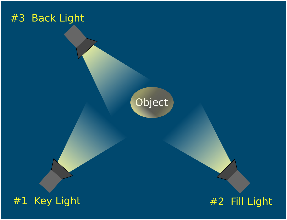
Three Point Lighting Setup


    Key Light: Your major light, should light up the majority of your object and also show off the most important stuff. 
    Think about sculpting with light. Shadows are just as important in showing off the dimensionality of your form. If there is too much light everything looks flat. 
    Tip for Rim light - it will generally opposite to your camera. It's supposed to separate your object from the background.
    Fill Light: used to lighten up shadows. Will have the lowest intensity out of all your lights. 

example of a bad rim light
    In this example, the light is no longer acting like a rim light as it is lighting up too much of the mesh. If this happens, we can go to two lights for the rim 
(still a 3 point setup, even if two lights are doing one job).
    When doing this setup, a good tip is to do key then rim then fill. Fill is last because it is doing the least amount of work.
    One of the most important parts of this is that you want the the extremes of both dark shadows and light highlights. You want to show off a wide spectrum instead of your values clustered in one area. 

Showing off your work

    In the bottom corner of Unreal, you can type: 
r.highresscreenshotdelay 100 
     This changes the time it takes to make a high resolution screenshot. The 100 determines the amount of time it will take to make a high resolution screen shot, it will cutoff the render after a certain amount of time.
    In the high resolution screenshot settings, screenshot size multiplier = 3.
    Make sure that the camera's focus is on your object. Go down to your camera's focus settings and use the eyedropper option to choose the object in your viewport. 

    Why do i have blotchy screenshots? possibly due to low samples. Low samples = less computation but more noise. You can change the sampling on the lights by going to ray tracing > samples per pixel. Change it by 4 to see if it helps. 

Monday, 6 January 2025

Tech Art Math Part 1

 Algebra, Geometry, Trigonometry

Slopes: tell us going from left to right or are you going up or down. Zero slope (horizontal) and Undefined slope (vertical).

Slope is Rise Over Run, (y2-y1)/(x2-x1).

Right Triangles: Types include Scalene (no sides are the same) and Isosceles (Two Equal sides at 45 degrees). Length of Hypotenuse calculated with the Pythagorean Theorem.

Sine, Cosine, and Tangent are definitions given to ratios of similar triangles. Remember SOHCAHTOA (Sine Opposite Hypotenuse, Cosine Adjacent Hypotenuse, Tangent Opposite Adjacent). 

Cosine helps to measure the x distance. Tangent is the pure ratio between the angles, when you don't know the hypotenuse.

Asin, Acos, and Atan is used when you know the ratio but don't know the θ angle instead. 

Unit Circles

    Unit circles are circles with a radius of 1, or a diameter of 2.

    Circumference = 2 * Radius * pi

    Area = pi * Radius * Radius

    Radian: unit of angle in the International System of Units (SI). An abstract amount. A dimensionless SI derived unit. 

    If you took the radius of a circle, and then shrink wrapped it to the surface of the circle, that would be 1 Radian. 180 degrees = pi radians. 360 degrees = 2pi radians.

    1 degree = 2pi radians / 360 degrees or 1 = pi radians / 180

    1 radian = 360 degrees / 2 pi Radians or 1 = 360 degrees / pi

    A lot of math libraries assume you work in radians.  

Circular Functions

sin θ = Y Component

cos θ = X Component

Remember Law of SIN: 

sin^2 θ + cos^2 θ = 1


Law of COS: a^2 = b^2 +c^2 - 2bc cos θ

If you don't have a right triangle you can use the Law of Signs

sin α / a = sin β / b = sin θ / c


Vectors

    A vector: one-dimensional Array representing the solution of a system of linear equations. An element of the real Coordinate Space Rn (a coordinate in space, like xyz). Vectors can be multidimensional (but that dimension should be defined). All vectors originate from the origin (although you can offset them to move them around).
    They represent positions in space (a point, but this will have a direction of 0).
    Colors are vectors. 
    Notations

Why is w at the end of the 4x1 or 1x4 vector? w is the Homogenous Coordinate. It defines if the vector is a direction (0)(think of it as the default) or a point in space (1). It helps to make the math work. In tech art, most of the time you'll be working with 4x1 or 1x4 matrices. 

Vector Operations

Vector Addition:

    You add corresponding components.  


     When you add two vectors, shouldn't the resulting vector be on top of the other? Technically it is, but since all vectors originate at the origin, the tail of the new vector comes from the origin.

Vector Subtraction

    Similar to vector addition, you subtract corresponding components. 

    For A-B Think 'what vector would I need to add to B to get to A.

Scalar Multiplication

    Multiply all the components of the vector by the scalar (a constant number)

Length (or Magnitude)

    Use the Pythagorean theorem to calculate the length. 
    Add up all the squares of the vector components then square root it. 
    The Pythagorean theorem does not work on points. The length of a point will always be zero. 

Normalizing

    Normalizing a vector makes it a unit vector. A unit vector is a vector with a length of 1. This makes it easy to use in calculations, as it only shows direction. Calculate the length of a vector, then divide each component by the length.
    Scalar has the length, D has the direction. Put a bar over the direction to show that it is a unit vector

Dot Product

    The Dot Product is the Sum of products of matching components. Produces a scalar value known as Scalar Product or Inner Product. Always a floating point value. 
    You can use it to find the angle between vectors, or to project one vector onto another. It is communitive, distributive, and associative. 

Vector Triangle Inequality

If you add two vectors and take the magnitude of them, it will always be less than or equal to the magnitude of two vectors added together.

Angle Between Vectors

Taken from the law of cosines

    If a and b are unit vectors, then their dot product is equal to the cosine of the angle between them (since their magnitudes are just 1, 1 times anything is itself. 
You will be seeing left handed and right handed coordinate space, depending on which one it is will determine which way vectors are pointing. 

Cross Product

    Performing the cross product between two vectors will produce a vector that is perpendicular to them. 

Matrices


     An ‘N’-Dimensional array of Numbers. Most typically N = 2
    Each "Straight Line" of a Matrix can be considered as "one" vector. Each column is a unique vector. Each row is a unique vector.
 

    Typically 'M' Rows and 'N' Columns. Described as a M x N matrix

Scalar Multiplication

    Each entry in Matrix multiplied against scalar

Addition and Subtraction

    Must have same number of rows and columns, else it is undefined. You will add or subtract corresponding components. (Similar to vector addition and subtraction). Addition is commutative, but subtraction is not. 

Transpose

    Rows become Columns and Columns become Rows
    What once was row vectors, have now become column vectors. 

Multiplication

    Take the Dot Product of rows and columns to produce components of corresponding matrix. This is associative but not commutative

    
The number of columns of the 1st matrix must equal the number of rows of the 2nd matrix. 
And the result will have the same number of rows as the 1st matrix, and the same number of columns as the 2nd matrix.

    Think if you have a 3x2 matric multiplied with a 2x3 matrix, you'll get a 3x3 matrix. (Think the inside values need to be the same, and the result will inherit the outside values)
3x2 * 2x3 = 3x3
1x3 * 3x5 = 1x5

Identity matrix

    Is there a matrix in that if we multiply anything it will equal itself. Yes the Identity matrix. The dimension of Identity is always square. 

Zero Matrix

    Any zero packed matrix which is defined to multiply against A. Just a matrix will full zeros. 

Matrix Inversion

    Is there an inversed matrix that when multiplied with it's original matrix will produce the identity matrix. 


    In order to get the inverse, the matrix has to be a square matrix. You'll also need the determinant. 
A determinant is a scalar-valued function to represent a matrix (like a magnitude for a vector)

Easy Notes Archive

 Tech Art Blueprints Demo Animation State Machines Part 1 Animation State Machines Part 2 Math for Tech Art Part 1 Math for Tech Art Part 2 ...