Monday, 21 April 2025

Shader Tool Week 5 - Shadow Mapping

     Shadow Mapping in 4 steps

  1. Projection Texture Mapping
  2. Occlusion Depth Mapping 
  3. Projection With Occlusion
  4. Shadow Mapping

Projection Texture Mapping

  • We're making the light into a camera with a view frustum. The projector is defined by its frustrum. Treat the light as if it were a came
  •  We need to transform its X, Y coordinates into NDC (Normalized Device Coordinate Space)
  • The range is [-1,1] but textures are mapped to range [0,1]
  •  Scaling Matrix u=0.5x +0.5, v = 0.5y+0.5
  • taking [u,v,0,0] and applying the NDC 4x4 matrix
  • We need the projective texture matrix
  • Doing this will transform any object into a projection. (Must be done in the vertex shader)
  • Then in the pixel Shader you'll have the ProjectedTextureCoordinate from the vertex shader. But it needs to be in NDC space. To do this, divide the ProjectedTextureCoordinate.xy by the w coordinate. 
  • Sometimes, you might get reverse projection, it'll appear to emit from either side of the frustrum of the light. You can fix this by verifying if the projected texture coordinate's w component is greater than or equal to zero (it is the z component, how far away it is from the light. We don't want to have a z component that is negative because that means it's behind the light.) Only project texture when: IN.ProjectedTextureCoordinate.w >= 0.0

Occlusion Depth Mapping/Projection With Occlusion

  • Objects being occluded will still receive the same projected texture so we need a depth map generated to test for occlusion. All objects in the scene needs to be tested against depth map (this can be very expensive)
  • These depth maps are rendered to Render Targets (buffers in space that store information in space for future uses, we did these last week). The closer an object is, the brighter the map. Black means it is the farthest away from the light.  You usually calculate the depth map in the vertex shader because it's faster and better precision. 
  • Shadow Acne: Shadow maps can be limited in resolution and depths are quantized, you'll get aliasing issues. When actual depths are compared against sampled depths, results can vary (Precision Error).
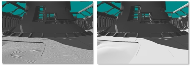
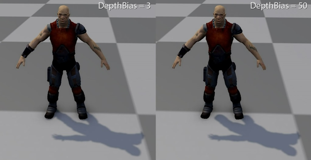
  • You can set the depth bias to help with shadow acne, it subtracts from the depth map sample by a tiny amount to help with the precision error. 

Shadow Mapping

    Instead of using a projected texture for the shadow map, just use the depth map rendered from the light as the shadow map for the object. 

Percentage Closer Filtering (PCF)

    Soften the edges of the shadow, it averages multiple depth map values using a convolution filter. 
    This is fat and slow. Sampling depth map repeatedly is expensive and slow. Direct3D 11 provides an intrinsic PCF function: SampleCmp.

Peter Panning

    An issue when the shadow appears disconnected. Happens when someone is trying to get rid of shadow acne and increases the depth bias too much. Typically occurs when Slope-Scaled Depth Biasing is not used. 


Monday, 14 April 2025

Shader Tool Week 4 - Post Processing

    Happens after we've rendered the main image.

    A render target is a memory buffer. It's a place that you can render an image to and then store it to the side so you can use it at a later time.

    Full Screen Quad: Instead of rendering the first pass to the screen buffer (the actual screen) first, You create two tris to make a rectangle that represents the screen. Then apply the current render target to the quad as a texture map. Then you re-render the full screen quad with a new FX shader on top of it. 


    Types of Post Process Operations

  • Matrix Operators: each pixel multiplied by a constant matrix
  • Convolution/kernel Operator: Pixel Value derived by neighboring input
  • Functional operators: pixel value calculated by a standard function

Grey Scale Filtering:

    You'd think we could just add up the rgb and divide by 3 to get the average grey. But actually the human eye sees reds, greens, and blues differently and need to adjust the weights accordingly. The equation is: 
    Intensity = (0.299*R + 0.587*G + 0.114*B)
    Use these values as a vector and use a dot product against the color vector of your scene
float intensity = dot(color.rgb, GreyScaleIntensity);

Inverse Filter

    For an inverse filter you'd just have to take the color and subtract it from one. 

Sepia Filtering

    Like old timey photographs, more brown than greyscale. 
    SepiaR = 0.393*R+0.769*G+0.189*B
    SepiaG = 0.349*R+0.686*G+0.168*B
    SepiaB = 0.272*R+0.534*G+0.131*B
    Use these values to create a matrix, and just multiple the matrix with your color vector. 
return float4(mul(color.rgb, SepiaFilter), color.a)

Generic Filter

You can really create a matrix for any filter. 

Bloom

    For bloom, you're calculating a threshold of the brightest area of your image, blurring that and then using that to add on top of the original image. 

Convolution Filter

    Often called kernel operator. A current pixel's value is an aggregate of it's neighboring values. You use a for loop to calculate offsets to the current pixel's coordinates and sample the pixel nearby to impact the current pixel's value. 
    Examples include box blur, gaussian blur, a sobel operator. 
    For gaussian blur it is more expensive but looks better. It's a two pass filter, first horizontally blurred and then vertically blurred. 

Sobel Operator

    Edge Detection, it looks for contrasts in adjacent pixels. It works on pixel illumination instead of color. It's a two pass filter (horizontal and vertical), if the sum of the two passes exceed a threshold Return white, else return black. 

Dithering

    Create for achieving that 90's 16 bit color look. 


Monday, 7 April 2025

Shader Tool Week 3 - Surface Mapping

 Texture Cubes

    Also known as cube maps, its 6 2D texture maps corresponding to the faces of an axis-aligned cube. Used in lighting a scene to project environment colors.


    There's a photoshop plugin that lets you create cubemaps. Make a long line of squares in the order of: +X, -X, +Y, -Y, +Z, -Z. Go to file> save a copy and change the file type to D3D/DDS. An interface will pop up asking how you want to configure it. With these settings:

  • 8.8.8.8 ARGB 32 bpp | unsigned
  • no mipmaps
  • cube map

A cubemap acts as if its center is at the origin. Stretching will occur if you move outside of it. 

    With cubemaps we're no longer dealing with just 2 u and v coordinates. We're using x, y, and z. We are going from the origin of the world and casting out a ray to the edge of the sphere. This gives you the xyz coordinate and it will be translated to the cubemap coordinates.

Structures for cubemap: the VS_OUTPUT struct includes a texture coordinate that's a float3 instead of a float2

/******** Data Structures ********/

struct VS_INPUT

{

  float4 ObjectPosition : POSITION;

};


struct VS_OUTPUT

{

  float4 Position : SV_Position;

  float3 TextureCoordinate : TEXCOORD;  // Returns Float3 not Float2

};

Vertex Shader:
/****************** Vertex Shader *********************/
VS_OUTPUT vertex_shader(VS_INPUT IN)
{
  VS_OUTPUT OUT = (VS_OUTPUT)0;

  OUT.Position = mul(mul(mul(IN.ObjectPosition, World), View), Projection);
  
  OUT.TextureCoordinate = IN.ObjectPosition.xyz;  // Working on Direction and not UV Position
  
  return OUT;
}
Pixel Shader: for a skyboxTexture sampler you need to input a float3 or else it will not work. 
/*************** Pixel Shader ***********************/
float4 pixel_shader(VS_OUTPUT IN): SV_Target
{
  return SkyBoxTexture.Sample(TrilinearSampler, IN.TextureCoordinate);
}

Environment Mapping/Mirror

    AKA Reflection Mapping. It approximates reflective surfaces, such as chrome. You need to compute the reflection vector for light hitting the surface. It is dependent on the view Direction and Surface normal. 
    When light hits a surface, it creates a reflection vector. That vector goes off and hits the cubemapped sphere's surface. The color that the vector hits can be sent back to the surface to be used as a reflection. 
formula:
R = I-2*N*(I*N)

There is a reflect intrinsic function in HLSL that computes the reflectionv vector for you. 
Data Structs
/******** Data Structures ********/
struct VS_INPUT
{
  float4 ObjectPosition : POSITION;
  float2 TextureCoordinate : TEXCOORD;
  float3 Normal : NORMAL;
};

struct VS_OUTPUT
{
  float4 Position : SV_Position;
  float2 TextureCoordinate : TEXCOORD;
  float3 ReflectionVector : TEXCOORD1;
};
Vector, here we're using the reflect function:
/****************** Vertex Shader *********************/
VS_OUTPUT vertex_shader(VS_INPUT IN)
{
  VS_OUTPUT OUT = (VS_OUTPUT)0;

  OUT.Position = mul(mul(mul(IN.ObjectPosition, World), View), Projection);
  OUT.TextureCoordinate = get_corrected_texture_coordinates(IN.TextureCoordinate);
  
  float3 worldPosition = mul(IN.ObjectPosition, World).xyz; //Only Direction
  
  float3 incident = normalize(worldPosition - CameraPosition);
  float3 normal = normalize(mul(float4(IN.Normal,0), World).xyz); // Only the direction
  OUT.ReflectionVector = reflect(incident, normal);        // HLSL Intrinsic Function
  
  return OUT;
}
Pixel, if a cube map is used as an environment map you need to use Environment Map sampler:
/*************** Pixel Shader ***********************/
float4 pixel_shader(VS_OUTPUT IN): SV_Target
{
  float4 OUT = (float4)0;
  
  float4 color = ColorTexture.Sample(TrilinearSampler, IN.TextureCoordinate);
  float3 ambient = get_vector_color_contribution(AmbientColor, color.rgb);
  float3 environment = EnvironmentMap.Sample(TrilinearSampler, IN.ReflectionVector).rgb;
  float3 reflection = get_vector_color_contribution(EnvColor, environment);
  
  OUT.rgb = lerp(ambient, reflection, ReflectionAmount);
  OUT.a = color.a;
  
  return OUT;
}
you can see the reflection of the environment map here

    Many environment maps don't match object or scene. The solution is a dynamic environment maps. Per Frame: it drops camera with 90 degrees FOV and render each of the six orthogonal directions. This is very expensive and very slow, only use for primary object and render at lower resolution. 

Fog

    Objects fade into background as distance increases. Need to know where fog begins and how long for obscurity. The amount of light from fog is needed also.
v is distance from camera from surface
FogAmount = (|V} - fogStart)/FogRange
Color(final) = lerp(litColor, FogColor, FogAmount)

/*********** Utility Function ****************/
float get_fog_amount(float3 viewDirection, float fogStart, float fogRange)
{
  return saturate((length(viewDirection)- fogStart)/fogRange);
}
    This gives us a ratio of how much fog is there for us to lerp with. length(viewDirection) gives us a vector of how far away the surface of an object is away from the camera. Aside from this, its just phong lighting again.

    Color Blending

    When frame buffer alrady has a color value and a new pixel color is blended. HLSL BlendState objects behave similar to rasterizer states. New Color is Source. pre exisitng color is destination. 
output layering = (Source*Factor)*Operator*(Destination*Factor)


Saturday, 5 April 2025

LIGHTING ISSUES

 To set up to bake lighting: 

  • Project Settings:
    • Engine - Rendering: 
      • Allow Static Lighting to True
      • Disable Lumen: Change global dynamic illumination to None
  • To ensure:
    • Post Process Volume
      • Global Illumination Method: None
      • infinite extend: True
    The default level in UE5 is based on the Open World template, with the World Partition. Meaning that Baked Lighting does not work with it. (5.5 and beyond says that it works with baked lighting).
    NOTE: if you try to test baked lighting in a basic level, you have to delete the floor that comes with it. Baked lighting doesn't work on it.
    Make sure Force No Precomputed Lighting is turned OFF
    Check the lightmap density of objects in the scene, go to View mode > Optimization Viewmodes > Lightmap Densities

Common Art Sprint #4 Delivery

   Responsible for:  updating the jinroh model with the newest model  updating gun model with new uvs adding ik controls onto the ammo gunbe...